
© DL4FG Weilburg
Building instruction "Electronic roulette" (without microcontroller)
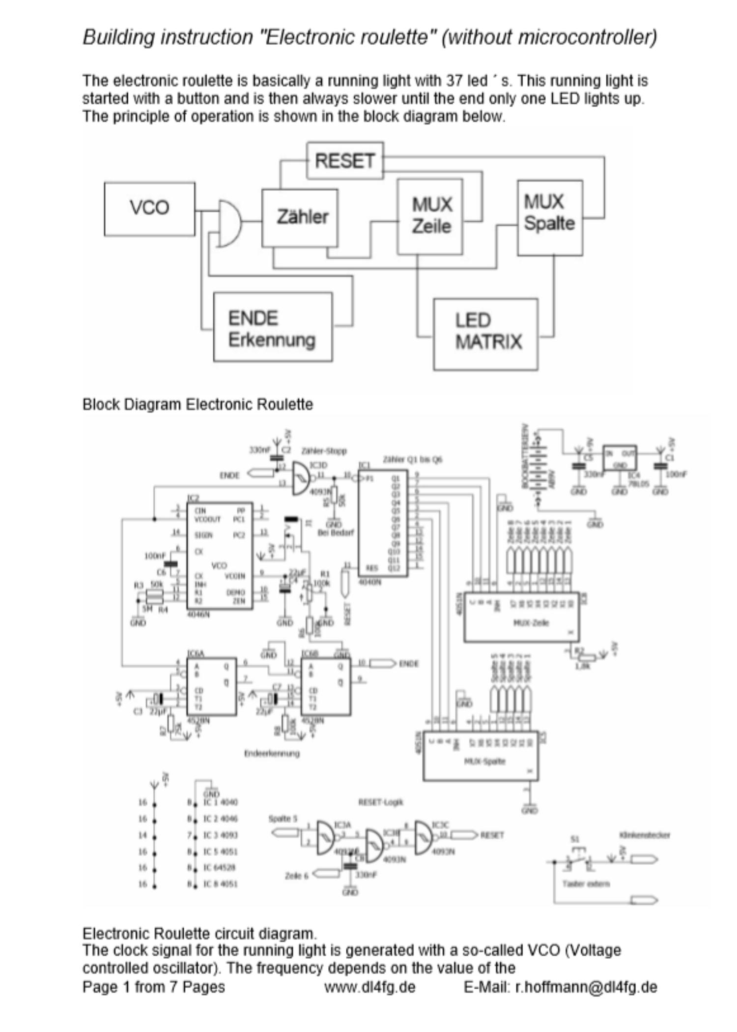
The electronic roulette is basically a running light with 37 led ´ s. This running light is started with a button and is then always slower until the end only one
LED lights up. The principle of operation is shown in the block diagram below.
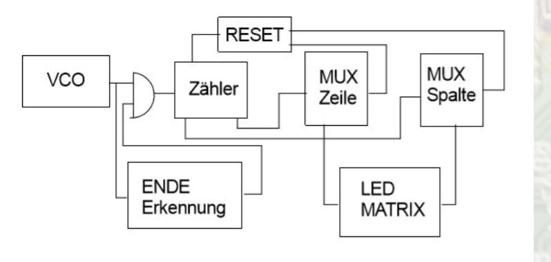
Block Diagram Electronic Roulette
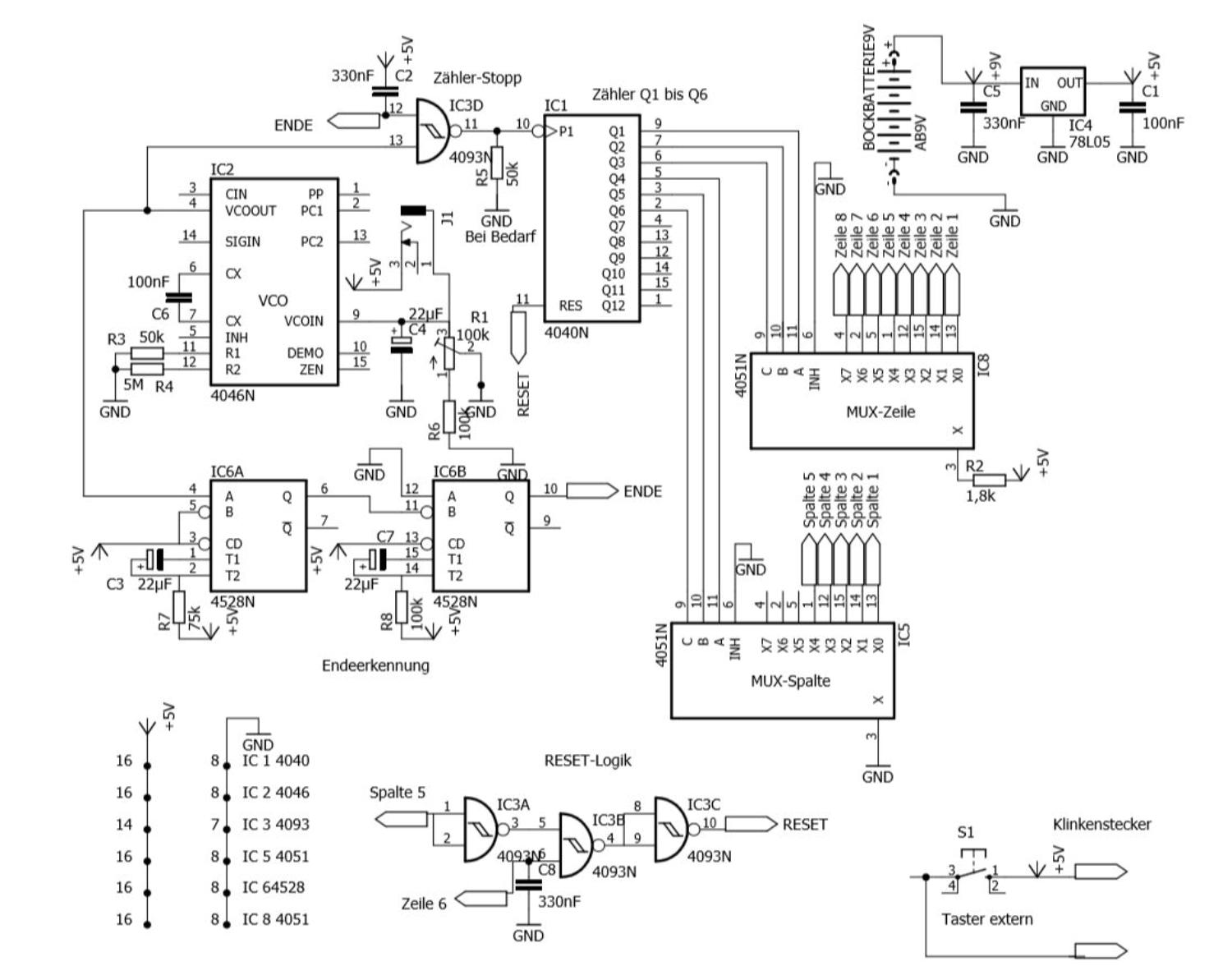
Electronic Roulette circuit diagram.
The clock signal for the running light is generated with a so-called VCO (Voltage controlled oscillator). The frequency depends on the value of the
Control voltage. For electronic roulette, the frequency is further reduced in order to slow down the running light. In the present circuit, the anode of an
electrolyte capacitor with a parallel connected trim potentiometer to the control input pin 9 of IC 2 (4046) is connected. The button for starting the
running light sets the operating voltage to pin 9 and charges the electrolyte capacitor. After releasing the button, the electrolyte capacitor unloads via
pin 9 and the parallel resistor. This reduces the frequency of the VCO ´ s to almost 0 Hz. The output signal passes through a NAND gate (IC3/4) to a
12stage binary divider IC1 (4040). Only the bit ´ s 1 to 3 and 4 to 6 are used by this divider. The first 3 bits are connected to the inputs A, B and C of an
analog multiplexer (MUX) IC 8 (4051). The multiplexer switches the signal to pin 3 of the MUX to one of 8 outputs depending on the bit combination. This
MUX controls the 8 lines of an 8 x 5 matrix. It provides a limited current of approx. 2mA to the anodes of the LEDs in the matrix via a resistor R 2
(1,8k).
The second MUX IC 5 (4051) is controlled by bits 4 through 6 of the divider. It switches a ground potential to one of the 8 outputs of the second MUX
depending on the combination of the 3 bits. The output signal is on the columns of the LED matrix. Here the cathodes of the LEDs are connected.
In order for the divider to start again at 0 after the 37. Led is lit, the divider must be reset. The reset signal is generated by a logic from the signal of
the sixth row and the fifth column. This position of the 6th row and the 5th column would correspond to the 38. Led. The Reset logic with IC 3/1 to 3/3
provides a positive reset-signal to pin 11 of the divider IC 1.
Since the VCO IC 2 (4046) does not get down to 0 Hz one end of the running light has to be done in other ways. In this circuit the increasing impulse
duration is used for a stop of the running light.
A retriggerable Monostable Multivibrator IC 6 (4528) is triggered with the VCO output signal. As long as the pulse duration of the VCO signal is shorter
than the length of the Monostable Multivibrator, a constant voltage will be present at the output of IC 6. This is because the shorter impulse of the VCO
´ s will trigger the Monostable Multivibrator again before the time has ended (retriggering). If the pulse duration of the VCO signal is longer than the
time of the Monostable Multivibrator set by R 7 and C3, a pulse will appear at the output of the Monostable Multivibrator. This impulse now triggers a
second Monostable Multivibrator with a much longer active duration as the input signal. This will result in a constant low level at the pin 10 of the IC 6.
This low level is located at an input of the NAND gate IC 3 and locks the input signal to the divider IC 1.
The power supply is provided by a 9V block battery. The voltage is stabilized via IC 4 (78L05). The input voltage of IC 4 can be up to 30 V according to
the data sheet.
Should the running light run on its own after switching on, the resistor R8 ( PIN 14 IC 6) must be increased at the Monoflop.
The next page shows the circuit diagram of the LED matrix. It is important for diodes that they are led ´s with 2 mA power requirements. At led ´ S 20
– 30 mA are common. The lower power consumption also protects the battery.
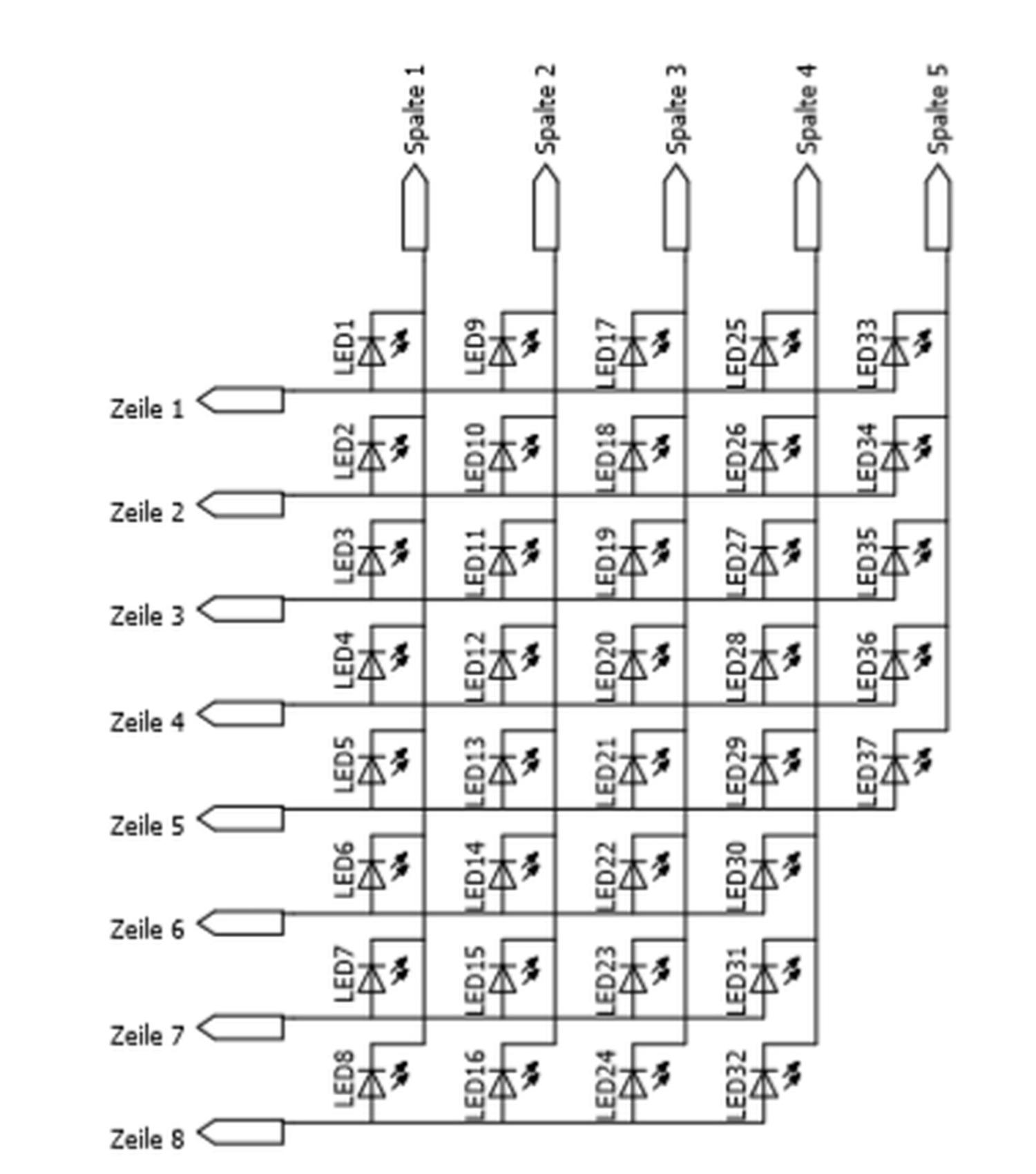
Circuit diagram of the LED-Matrix.
Structure of the circuit and corresponding housing.
The construction of the circuit was carried out on a 100 x 85 mm ² (3,94 x 3,35 squareinch) Hole Raster Board 1.5 mm thick made of hard paper with
pads from 35 µ copper pad.
At the corners I made holes of 3.5 mm diameter for the mounting of the board. The integrated circuits were put on pedestal by me after an old habit.
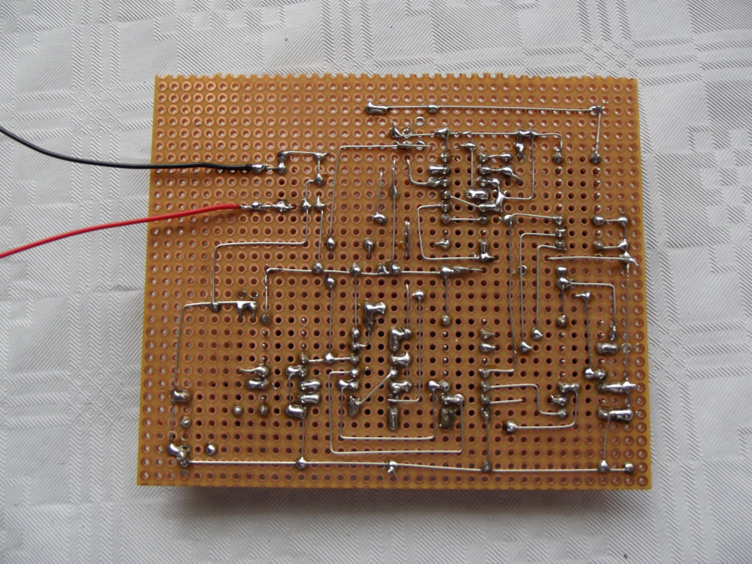
The connections between the connecting legs of the LED ´ s consist of a tin-plated switching wire with a diameter of 0.5 mm.
On the next page you can see the wiring diagram and the insertion plan for the hole Raster board. (Top View)
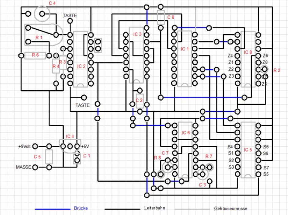
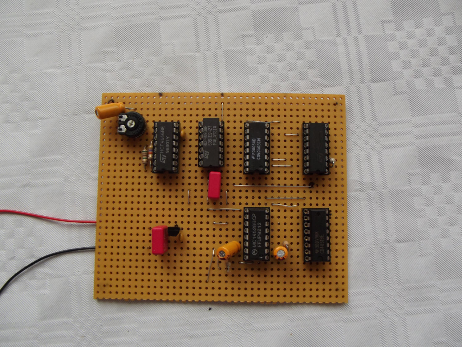
Top view
Bottom view (not nice but done)
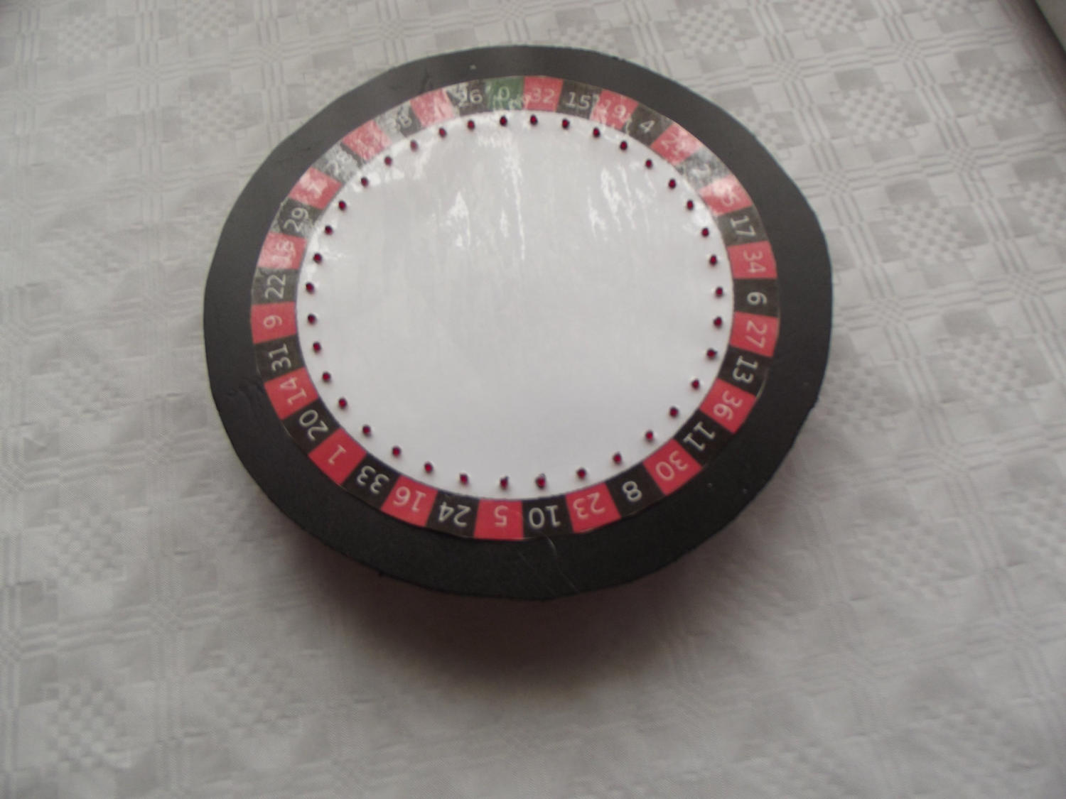
For the case I opted for a plastic flower pot coaster in Brown with a diameter of 21 cm ( 8,27 inch) and a height of 3cm (1,18 inch) . The top was cut out of
a plastic plate from the hardware store with a thickness of 3 mm (0,118 inch) and color black with a jigsaw. The diameter of this disc is based on the upper
diameter of the flowerpot.
I made the record stand out a bit and mark the center point. For this plate you can of course also take plywood, acrylic glass or something else suitable.
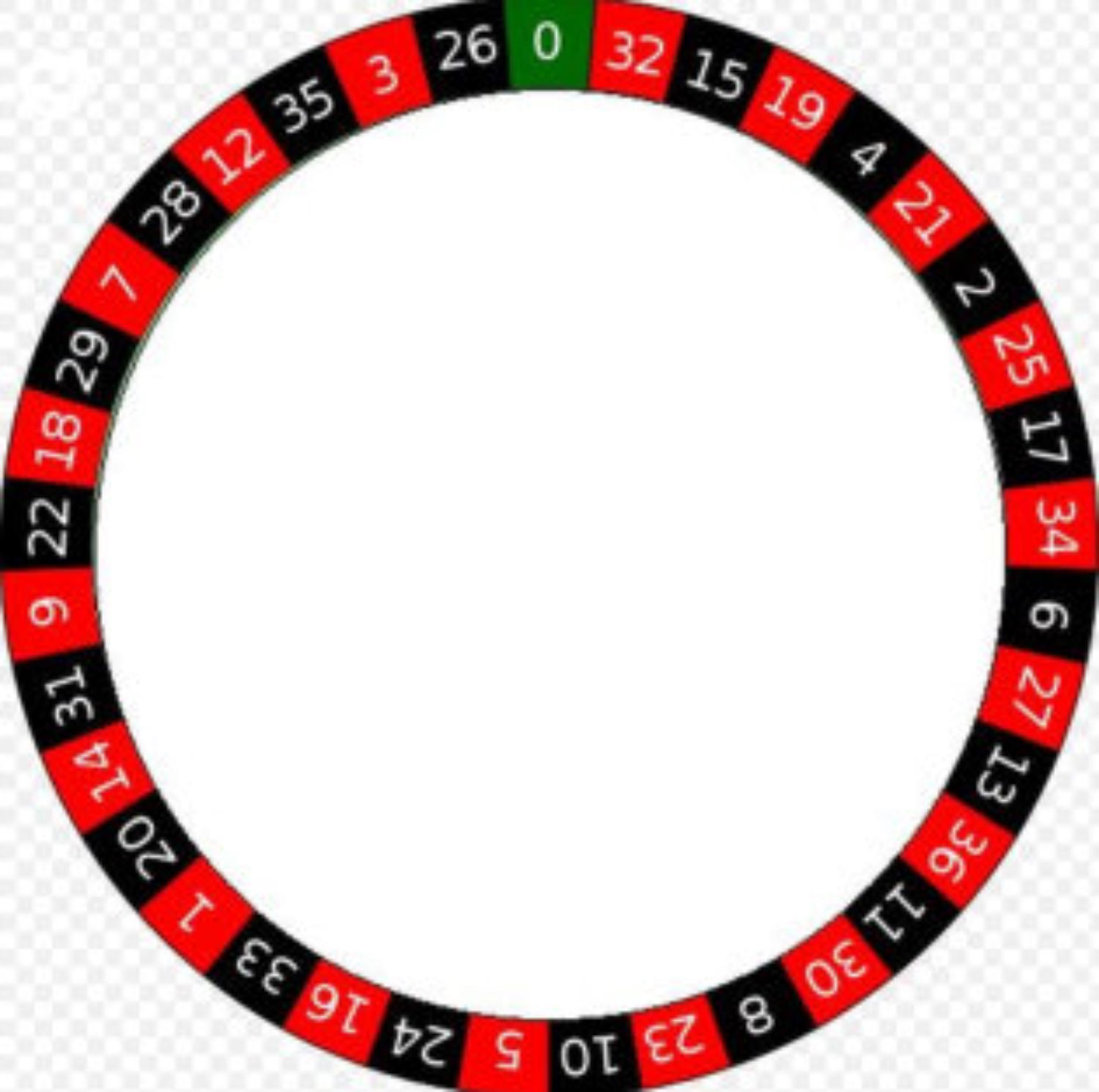
For the number margin I have discovered a template on Wikipedia, enlarged accordingly and provided as a download in PDF format. There is this number
margin in Din A4 and in Din A3.
I then laminated the printed number margin and cut it out in a circular shape. Now the foil was fixed with tape on the black disc and two arrow-shaped
markers, one on the plate and another on the foil glued.
Now the holes for the LEDs have been marked (thinner edding) and then drilled to 3 mm. When drilling through the laminate, small burrs were created
that almost completely disappeared with a hot soldering iron tip.
Now the film has been removed again and all holes are drilled to 4 mm (so that the LED ´ s better fit in.) Now the foil came back on the plastic plate and
was aligned with the markers.
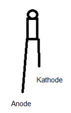
Now the diodes are inserted from the rear through the 4 mm bore. It should be ensured that all cathodes or all
anodes of the LEDs point towards the outside edge. This makes it easier to connect the cathodes to the switching
wire afterwards.
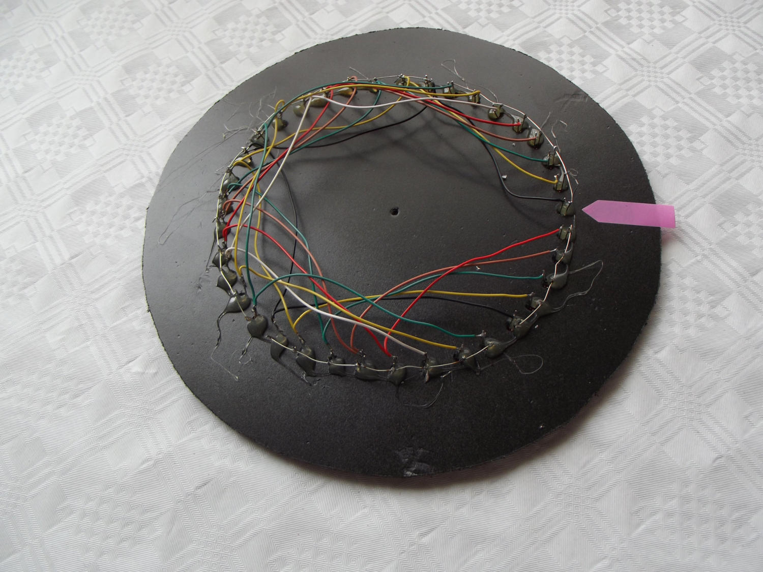
After mounting the LED I have glued it to the back with hot glue. Now it's about wiring. I have connected the first
eight cathodes clockwise with a bare switching wire, starting with the number 0 of the numerical margin. Then the
remaining led ´ S (8) occupancy led were connected to each other. At the end there were only 5 LEDs left.
Now the anodes of the LED are connected to the board. On the assembly plan, the numbers of the respective rows
and columns are marked with Z1-Z8 (lines) and S1 to S8 (columns) for the MUX blocks. The first line Z1 is
connected with the first led at the position 0 of the number wheel. Since the columns are recognizable on the
continuous connection, a connection must now be established between the first led of the first column and the first
led of the second column. All line outputs (Z2-Z8) are now connected to the LEDs from the first column. Now all
the LEDs of the remaining columns must be connected to the corresponding led in the first column. So the 3rd led
in column 3 is connected to the 3rd led in column 4 and the 3. Led in column 5, etc.
Connecting LED
The column signals S1 to S5 of IC 5 are connected with a wire to 8 led ´s, which are connected to their cathodes.
The button can be any model. He doesn't have to be bouncing either.
A toggle switch for on-off switching was fitted to the edge of the subframe and a 3.5 mm mono jack for connecting the switch.
Now follow a few pictures of electronic roulette.

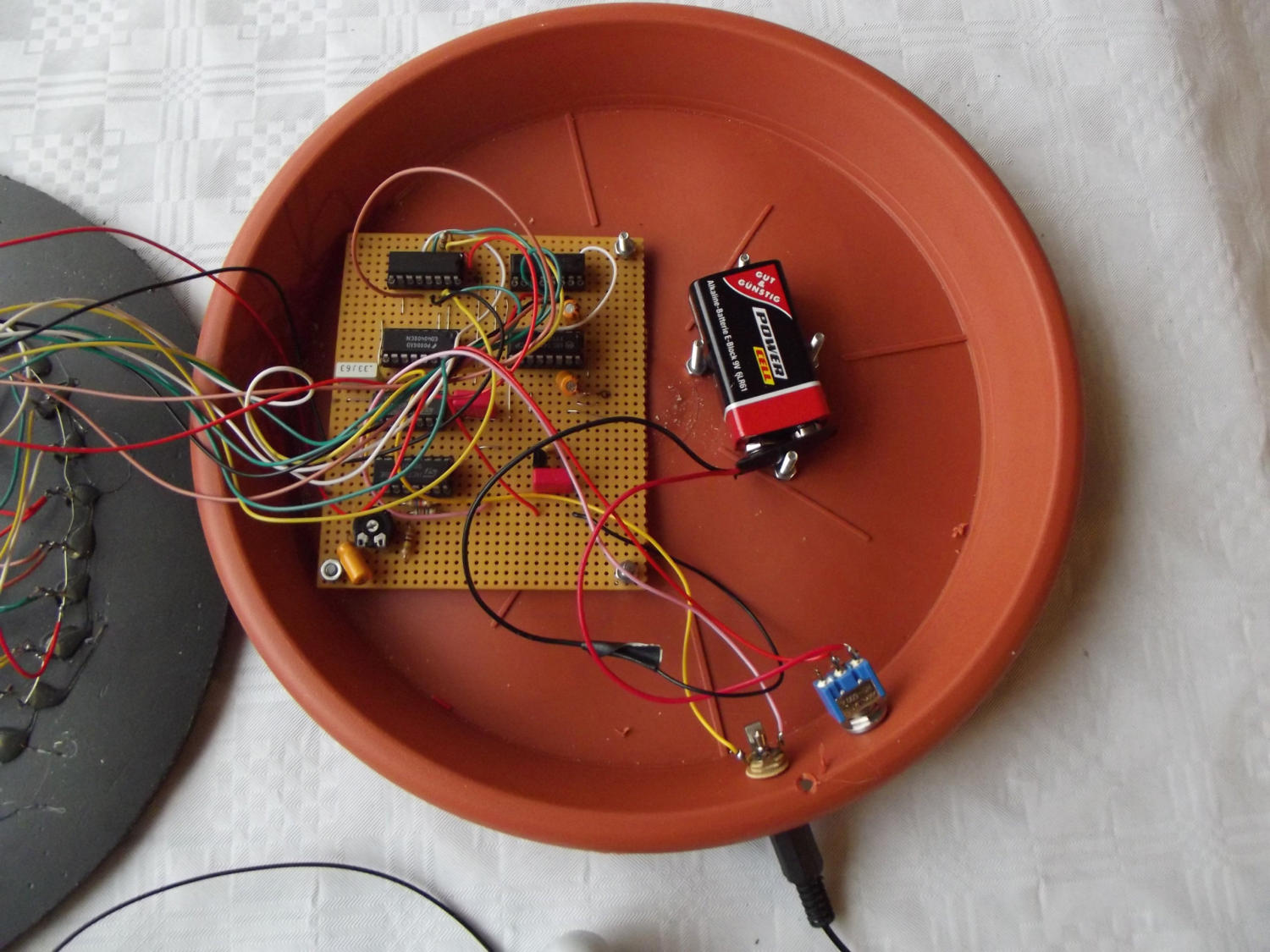
As the PCB protrudes over the middle of plastic flower pot coaster I have bent a small bracket on Alu flat profile and after laying the top part marked
the hole for the Alu-angle. Of course a hole of 3.5 mm diameter was first drilled into the upper plate. After a M3 thread was cut into the angle I screwed
the lid with a knurled screw M3.
Parts list for electronic roulette.
Other: Flower Pot Coaster, plate 3mm for housing top, mounting material, hot glue, wire, wire, laminate foil, Keybox mounting bracket, an extensive list of
electronics retailers follows the next building instruction.
Further questions: E-mail: r.hoffmann@dl4fg.de
Here begins the download area
Content:
Building Instructions Electronic Roulette
Filename:
RouletteENG.pdf
Filesize:
1.610KB
Comment:
Document size 210 x 297 (DIN A4) 7 pages
IContent:
Roulettedisc Diameter (7,87 inch) 200mm Printsize DIN A 4 (Source Wikipedia)
Filename:
Roulette_2_DINA4.pdf
Filesize:
867KB
Comment:
Document size 210 x 297 (DIN A4) 1 Page
Content:
Roulettedisc Diameter 270mm Printsize DIN A 3 (Source Wikipedia)
Filename:
Roulette_2_DINA3.pdf
Filesize:
1.400KB
Comment:
Document size 297 x 420mm, DIN A3 1 Page
PS: Thank you for your patience.


German
Amateur Radio
Building site


© DL4FG WEILBURG
Die Hilfe ist nah.
Hier erhaltet Ihr ein paar Tipps zum Umgang mit der Website.
Die meisten Bilder können vergrößert werden. Dazu müssen die Bilder
nur angetippt oder mit der linken Maustaste angeklickt werden. Dann
erscheint am oberen Bildrand ein mehr oder weniger sinnvoller
Kommentar. Ein weiteres antippen oder anklicken verkleinert das Bild
wieder.
Alle Wörter oder Texte, die blau geschrieben und unterstrichen sind,
sind so genannte Hyperlinks (oder einfach nur Links). Wenn sie
angetippt oder mit der linken Maustaste angeklickt werden erscheint
eine externe Internetseite. Der Inhalt dieser Seite passt meistens zu
dem entsprechenden Thema. Zurück kommt man durch anklicken eines
Pfeiles nach links in der oberen linken Bildschirmecke.
Die Bildergalerien mit den Punkten am untere Bildschirmrand lassen sich
nicht vergrößern. Die Bilder werden weiter geschaltet durch antippen
der linken oder rechten Seite des Bildes oder durch anklicken der
transparenten Pfeile an den Seiten. So lässt sich sowohl vorwärts oder
rückwärts blättern.
Hinweise zu den unterschiedliche Browser-Typen.
Internet Explorer: Keine Probleme.
Mozilla Firefox: Die Wörter, die als Links blau und unterstrichen
angezeigt werden erscheinen hier zum Teil als dunkelgraue
unterstrichene Wörter. Die Links gehen aber.
Google Chrome: Keine Probleme.
Opera: Wörter, die als Links dienen sind teilweise dunkelgrau. Links
funktionieren aber.
Microsoft Edge: Keine Probleme.


Englisch
Hilfe